


What is a vacuum lifter?
A vacuum lifter raises heavy loads by creating a pressure differential between the suction cups and the load surface. Unlike conventional lifting equipment, it does not rely on a hook, mechanical clamp, or electromagnetic attachment to hold the workpiece. It can still achieve the grasping of workpieces. During operation, the suction cup directly adheres and presses tightly onto the surface of the workpiece. The air remaining between the suction cup cavity and the contact surface is evacuated. After a negative pressure is formed inside the cavity, the external atmospheric pressure will press the suction cup firmly onto the material surface. No additional mechanical locking structure is needed throughout the process. After the suction cup has formed a secure seal with the workpiece, the load can be raised and moved from a crane lifting point. For short-distance handling, it may also be moved manually.
How does a vacuum lifter create lifting force?
Workpieces with very smooth surfaces allow the suction cup, once correctly set down, to push out most air at the contact face. Pressure outside the cup exceeds the pressure inside. This differential generates the holding force over the usable pad contact area.
In practical handling, the available lifting force is influenced by:
- the effective sealing area of each pad;
- the vacuum level maintained in the circuit;
- pad material, condition and contact geometry;
- surface flatness, porosity, oil, dust, moisture and coating condition;
- load orientation, centre of gravity and the forces created during acceleration or rotation.
Bigger suction pads alone cannot guarantee safe lifting. If the workpiece surface leaks, bends too much, or fails to maintain full continuous contact, the effective holding force will drop. For this reason, the contact surface must be evaluated together with the load size and handling frequency.
The operating sequence of an industrial vacuum lifter
Most crane-supported vacuum lifters follow a controlled sequence:
- Position the lifter. The frame is lowered so that the pads rest squarely on the approved lifting surface.
- Establish vacuum. The pump, compressed-air vacuum generator or other power arrangement evacuates the pad circuit.
- Verify holding condition. The operator confirms that the required vacuum condition has been reached before lifting.
- Lift and transfer. The crane, hoist, jib or rail moves the combined lifter and load within the approved travel path.
- Place the load. The workpiece is fully supported at its destination before vacuum is released.
- Release deliberately. A controlled release function separates the pads only after the load is stable.
The exact controls vary by configuration. Some applications require a compact self-suction device; others need powered vacuum generation, multiple circuits, warning devices, reserve energy or tilt-and-rotation functions. These features must be specified against the risk and duty of the application.
Main components and their functions
Suction pads and seals
Suction pads provide the contact interface. Their diameter, shape, lip design and elastomer material are selected for the workpiece surface and temperature range. Pad placement must also limit local stress and control deflection in thin or long sheets.
Vacuum generation and distribution
Vacuum is generated by a vacuum pump, pneumatic venturi generator, or alternate source. Distribution lines (hoses, valves, filters, manifolds) route negative pressure to each suction pad. The system is designed to maintain rated vacuum level across uneven work surfaces and variable site conditions - for porous materials, sufficient flow rate is the critical selection parameter.
Lifting frame and suspension
The lifting frame will distribute the load it carries over the entire supporting area of the lower base plate. The upper interface can be connected to the crane hook, sling or track trolley according to the actual working conditions. The structural parameters of the frame need to correspond to the actual size of the workpiece, the center of gravity position, and the operation direction of the lifting requirements. When conducting the verification of the lifting system, the self-weight of the lifting device and the available lifting height space on site must all be included in the calculation scope as inspection items.
Monitoring and release controls
Vacuum indication and warnings help the operator identify an inadequate holding condition. Depending on the application, the safety arrangement may include separate vacuum zones, non-return valves, controlled release, reserve power or other protective functions. The necessary arrangement is determined by the load, orientation, operating area and applicable site rules.
Vacuum lifter types by material and process
The lifting principle remains similar, but the contact surface and process requirement change the configuration.
Industrial Vacuum Lifting System
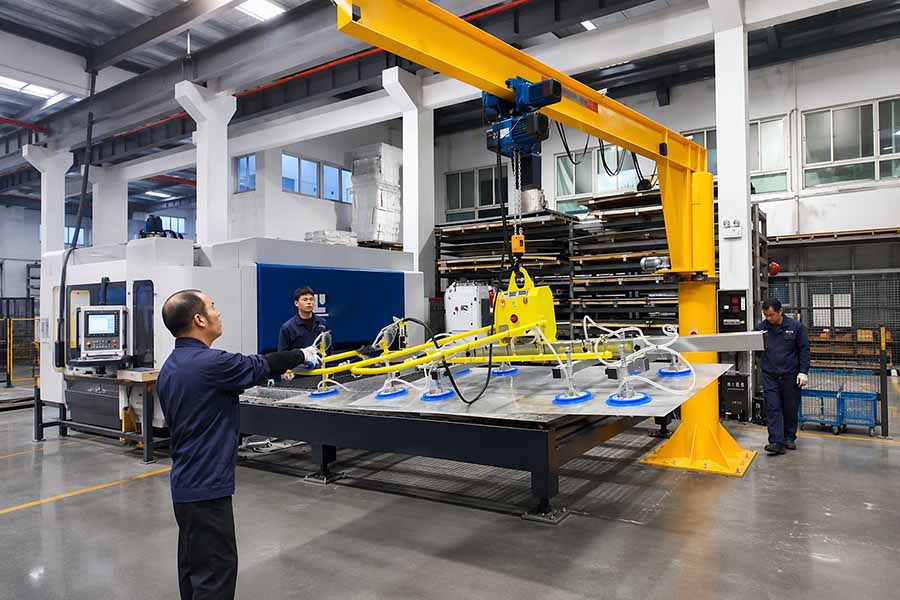
An industrial vacuum lifting system runs on a crane, hoist, rail track or workstation structure. Its job is the repeated transfer of sheets, panels, coils and custom-formed parts. Specifying one means working through a list: the material, dimensions, maximum weight, surface condition, load orientation, travel path and the power supply available on site. Leave any of these out and the specification drifts.
Sheet Metal Vacuum Lifter
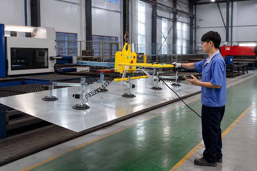
A sheet metal vacuum lifter picks plate or thin sheet up from the top face - the surface where hooks, clamps and magnetic contact would otherwise leave marks or distortion. How the pads are laid out matters a lot, because thin sheet can flex between individual contact points. The configuration has to be checked against the smallest, largest and thinnest parts in the handling range, not against the heaviest plate alone.
Glass Vacuum Lifter (Industrial)
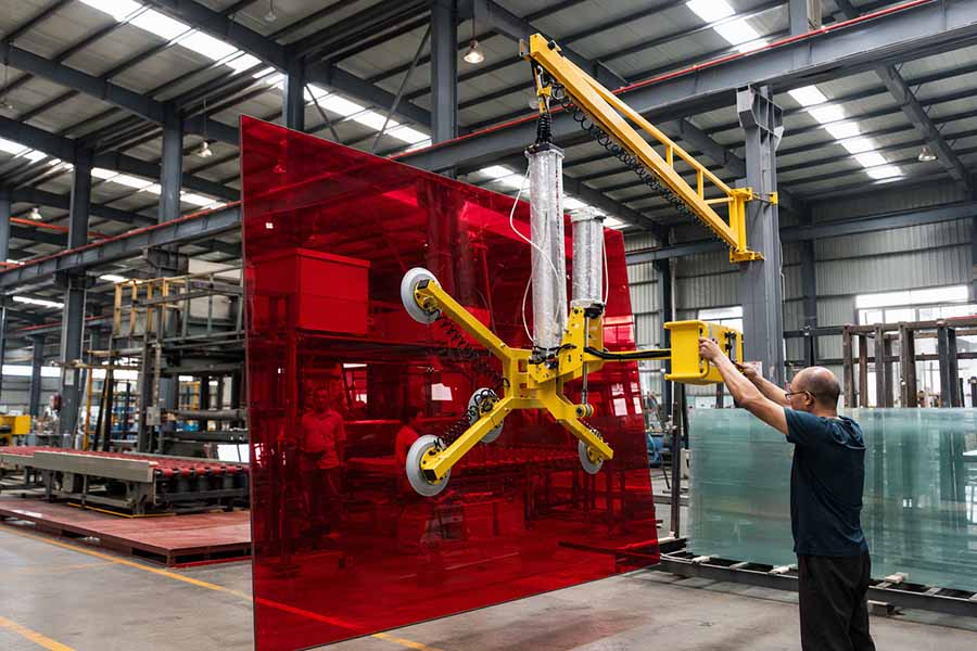
An industrial glass vacuum lifter is built around pad profiles and frame movement suited to glass handling and installation. The glass type, panel size, edge clearance, surface cleanliness and the tilt or rotation functions required all determine the layout. A configuration validated on flat glass should not be assumed to work on curved, insulated or coated glass without a separate technical review.
Concrete/Stone Vacuum Lifter
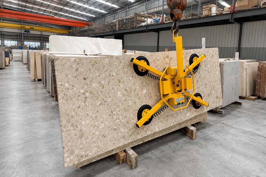
With a concrete or stone vacuum lifter, porosity, surface texture, dust and edge quality all get close scrutiny. Natural stone and concrete parts often do not offer a uniform sealing face. Testing and an application-specific appraisal are required before the lifter is put onto regular production work.
Vacuum Tube Lifter (Ergonomic)
An ergonomic vacuum tube lifter is used for frequent, hand-guided moves at a workstation. The vacuum tube itself carries the load, and the operator steers it through a control handle. This is a different handling idea from a crane-hung spreader lifter, and it is chosen according to material flow, lifting frequency, operator reach and the load interface.
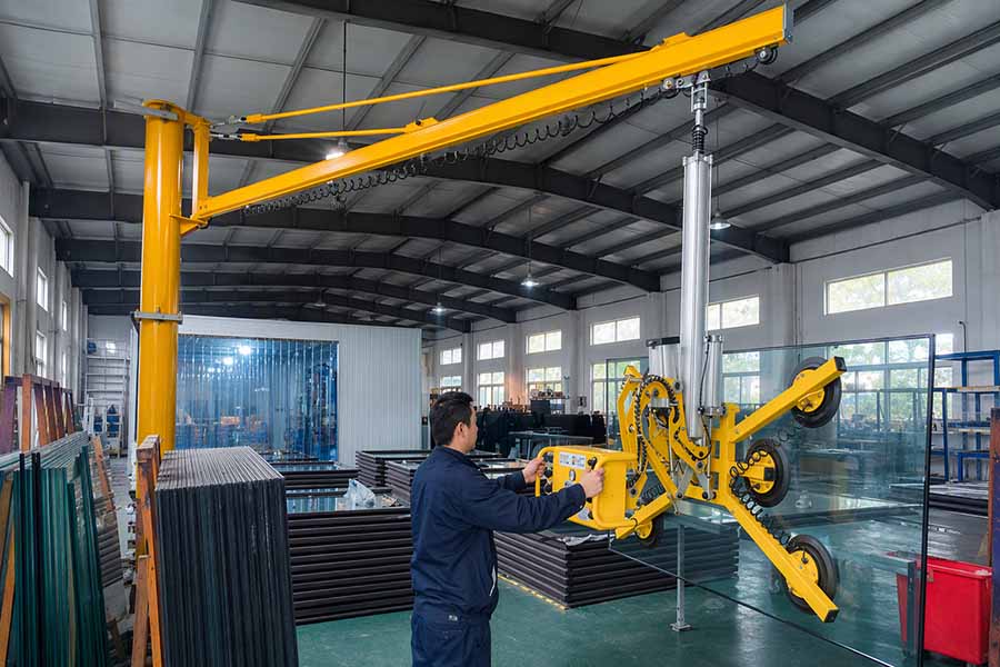
Selection data that should be confirmed first
A technically useful enquiry should define the complete handling condition:
- Workpiece material, finish, porosity and temperature.
- Maximum and minimum dimensions, thickness and mass.
- Centre of gravity and permitted pad-contact zones.
- Required lift direction, tilt, rotation and travel distance.
- Surface contamination, humidity, dust and leakage risk.
- Duty cycle, lifting speed and working environment.
- Supporting crane, hoist, rail or fork interface, including available headroom.
- Site safety rules, inspection requirements and installation constraints.
Conclusion
The working principle of the Vacuum lifter is simply to maintain a controlled pressure difference between the suction cup and the lifted material. Only by ensuring the sealing between the two, the proper distribution of the suction cup, and the compatibility of the equipment with the material and the process, can the reliability of the vacuum lifter be guaranteed. In summary, a reasonable selection assessment requires comprehensive consideration, so as to make a reasonable choice.


