


A lifting electromagnet uses controlled electric current to create a magnetic field that grips ferrous material. When integrated with a crane or hoist, it can move steel plate, billet, scrap, sections, and other magnetically responsive loads without slings, chains, or mechanical gripping points.
The lifting electromagnet working principle is straightforward, but dependable application depends on more than energising a coil. Load geometry, material condition, contact area, temperature, residual magnetism, power continuity, and crane motion all influence the result. The magnet, crane, electrical controls, and operating method must therefore be assessed as one lifting system.
What Is a Lifting Electromagnet?
A lifting electromagnet is an electrically energised lifting attachment designed for ferrous loads. It normally consists of a coil, a steel magnetic circuit, a wear-resistant contact face, a suspension arrangement, and an electrical connection to a suitable control and power supply system.
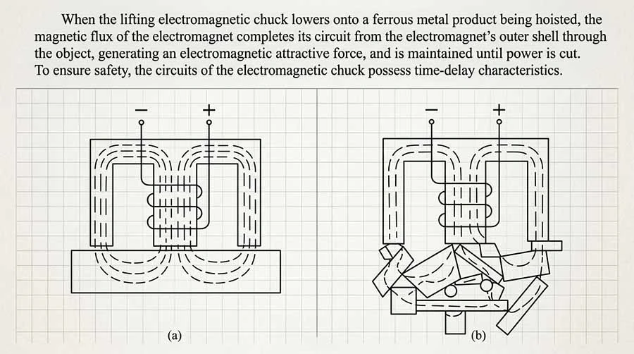
When current passes through the coil, the magnetic circuit becomes magnetised. The magnetic field travels through the magnet body, crosses the air gap at the contact face, enters the load, and returns through the magnetic circuit. This closed path produces an attractive force between the magnet and the ferrous workpiece.
Unlike a permanent magnet, an electromagnet is controlled electrically. The operator can energise the magnet to pick up a load and de-energise it to release the load. This controllability makes electromagnetic lifting suitable for repetitive handling processes where material form and workflow are well defined.
Lifting Electromagnet Working Principle
1. Electrical energy energises the coil
The operating sequence begins when the control system supplies current to the magnet coil. The current creates a magnetic field around the windings. The coil design, power supply characteristics, and duty cycle are selected for the intended lifting application.
2. The magnetic circuit directs the field
The steel body and pole structure guide the magnetic flux toward the working face. A sound magnetic circuit provides a low-resistance path for flux within the magnet and through the load. Any interruption in this path reduces effective attraction.
3. The load completes the magnetic path
A ferrous load positioned against the contact face becomes part of the magnetic circuit. The quality of contact matters. Rust scale, paint, curvature, gaps, uneven surfaces, and thin material can increase magnetic reluctance and reduce available lifting capability.
4. The crane lifts only after secure attachment is confirmed
After the magnet is energised and the attachment condition is checked, the crane or hoist raises the load. The lifting operation must follow the equipment instructions and the site lifting procedure. A magnet should not be treated as a universal substitute for mechanical lifting gear.
5. The load is lowered and released in a controlled area
The operator places the load on a stable support before release. The magnet is then de-energised according to the control sequence. Some ferrous materials may retain residual magnetism after release; this should be considered where clean separation or downstream handling is required.
Main Components of an Electromagnetic Lifting System
A complete system normally includes the following elements:
- Magnet body and pole face: Transfers magnetic flux to the workpiece and withstands normal contact wear.
- Excitation coil: Produces the magnetic field when supplied with electrical current.
- Suspension assembly: Connects the magnet to the crane hook, spreader, or other approved lifting interface.
- Power cable and cable protection: Delivers electrical power while accommodating hoisting and travelling movement.
- Control equipment: Provides energise, release, indication, and any specified protective functions.
- Crane or hoist: Positions and lifts the magnet-load assembly within its approved operating limits.
- Emergency power or holding provisions, where specified: Supports the required response to a loss of normal power. The required arrangement must be determined for the application and local safety requirements.
The Electromagnetic Crane Hook/Lifter is therefore not only a magnet. It is an interface between electrical control and crane lifting equipment. Compatibility of the suspension method, cable routing, power supply, and control logic must be verified before operation.
Factors That Affect Magnetic Lifting Capability
Magnetic lifting capability is application-specific. A value established for one material form cannot be assumed for another. The following conditions require engineering attention.
Material chemistry and magnetic properties
Electromagnets are intended for ferrous materials, but response varies between grades and conditions. The material must have sufficient magnetic permeability for the intended lift. Austenitic stainless steels and non-ferrous metals are generally not suitable for conventional electromagnetic lifting.
Contact area and surface condition
A clean, flat, close-fitting surface provides a more effective magnetic path than a surface with gaps. Scale, burrs, coatings, corrosion, dents, and debris can materially change the holding condition. For plate handling, thickness and flatness must also be considered.
Load shape and centre of gravity
Long products, bundled sections, irregular scrap, and asymmetric workpieces can shift or rotate when lifted. The magnet arrangement must control the load, not merely attract it. Multiple magnets, a spreader arrangement, or a different lifting method may be necessary where the load cannot remain stable.
Temperature and operating environment
Hot material can affect magnet performance and component life. Ambient temperature, radiant heat, dust, moisture, cable exposure, and work cycle should be defined during selection. A magnet designed for cold material must not be assumed suitable for elevated-temperature lifting.
Air gap and stacking condition
Every gap between the magnet and load weakens the magnetic circuit. In scrap handling, gaps arise from irregular shapes and voids within a pile. In plate handling, gaps can arise from surface distortion or interleaving. The actual handling condition, not an ideal flat test surface, should govern selection.
Common Types and Their Working Roles
Industrial Lifting Electromagnet
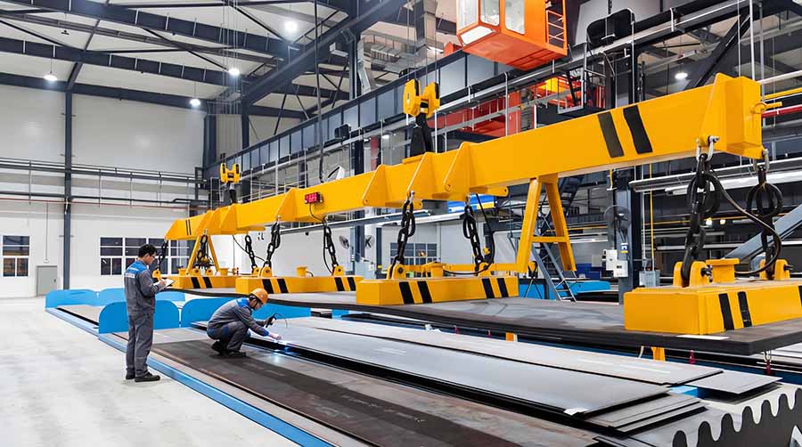
An Industrial Lifting Electromagnet is a broad term for magnets used in manufacturing, stockyards, fabrication, and material-processing operations. Configuration is selected around the material form, lift frequency, operating environment, and crane interface.
Circular Lifting Electromagnet
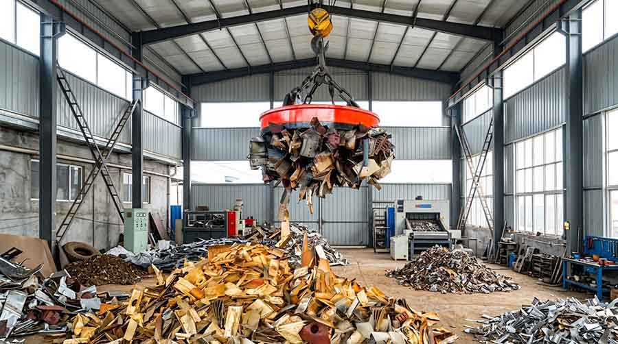
A Circular Lifting Electromagnet is commonly associated with irregular ferrous material, including loose and mixed shapes. Its circular contact area supports flexible engagement from different approach angles. Actual pick-up behaviour still depends on scrap density, material size, and the amount of metal in contact with the magnet face.
Scrap Lifting Electromagnet
A Scrap Lifting Electromagnet is applied where the load is discontinuous, irregular, or piled. The key engineering question is not nominal magnet force alone, but whether the magnet can achieve repeatable engagement with the real scrap profile while maintaining a controlled lifting operation.
Steel Lifting Electromagnet
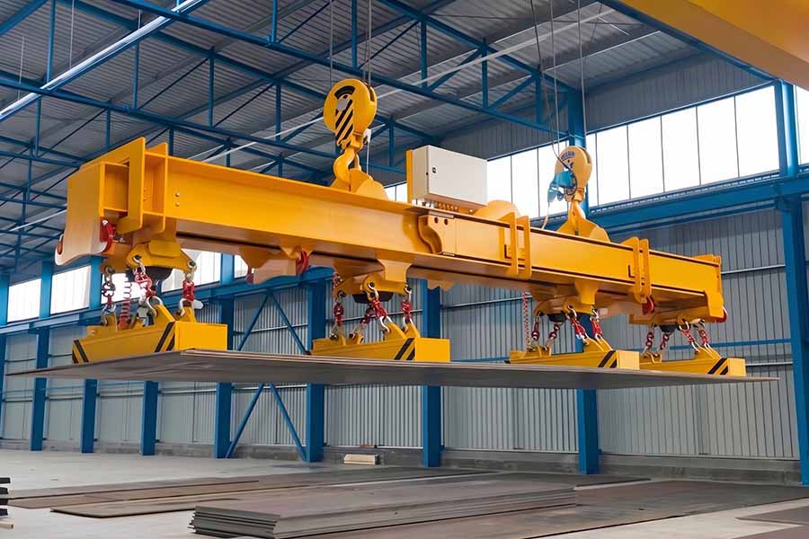
A Steel Lifting Electromagnet may be used for plate, slab, billet, bar, structural section, or other steel forms. Each form creates different contact and stability conditions. Plate handling often requires attention to thickness, sagging, and separation; long products require attention to deflection, balance, and multi-point support.
Frequently Asked Questions
Can a lifting electromagnet lift any metal?
No. Conventional lifting electromagnets are intended for ferrous materials. Non-ferrous metals and some stainless steel grades may not respond adequately. Confirm the material and the intended application before selection.
What happens if power is interrupted?
The required response depends on the system design and site safety requirements. Some applications may require emergency holding or backup power provisions. This must be specified, installed, tested, and maintained for the actual lifting duty; it must not be assumed.
Can one magnet lift several steel plates?
Only when the plate condition, thickness, surface contact, and separation behaviour have been assessed for that load case. Thin, oily, warped, or poorly contacting plates can create an unsafe condition. Use an approved handling method for the specific plate stack.
Is a circular magnet suitable for all scrap?
No. Scrap density, shape, size distribution, gaps, and temperature influence engagement. A Circular Lifting Electromagnet must be selected and operated for the actual scrap stream rather than a theoretical uniform load.
When should a mechanical lifting method be used instead?
Use a suitable mechanical method when the material is non-magnetic, the contact area is insufficient, the load cannot be stabilised, or the lifting condition falls outside the approved electromagnetic lifting envelope.
Conclusion
The lifting electromagnet working principle is based on a controlled magnetic circuit: electrical current energises the coil, magnetic flux passes through the magnet and ferrous load, and the crane moves the attached workpiece. Reliable operation, however, depends on material contact, load stability, system integration, and disciplined controls.
For any new application, define the real load condition, operating environment, power-loss response, crane interface, and safety requirements before equipment selection. This approach supports a lifting system that is suitable for the task rather than one selected from nominal capability alone.


